Vector Fields
by Tuğrul Yazar | December 28, 2012 10:32
Back to the basics. I finally had time to test the vector fields components in Grasshopper[1]. It was a couple of updates ago, a new tool group emerged in the vector tab, introducing different types of vector fields to users. Then, these fields could be merged to form more complex effects. However, I created a very simple example of how we can use those components to distort a system (such as a regular tessellation). Using attractor forces (usually in geometric forms) is one of the fundamental concepts of parametric modeling today. A regular implementation requires reasoning on the distances between objects and manipulating them according to this reasoning. That works well if there is only one attracting force for every object. However, creating more complex effects by merging various attractors is more difficult, whereas vector fields might seem to represent a faster solution.
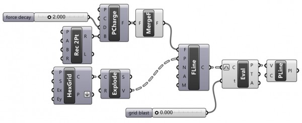 [2]
[2]Just put some points as charges, with a rectangular boundary. Then, combine them using the merge component, and create field lines of regular hexagonal grid vertices using this combined vector field.
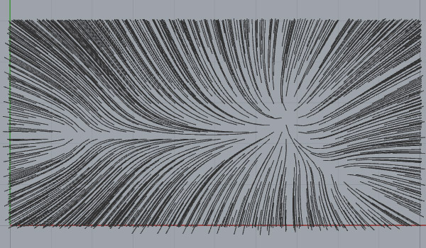
This is the field line[3] of the grid. Every point of the grid is represented as an “escaping” curve here. However, they keep the data tree structure for us to play with. I needed to create a controlled distortion according to these field lines. So, I evaluated them and played with the t parameter value. I rejoined these points in the data tree order and creating closed polylines again.
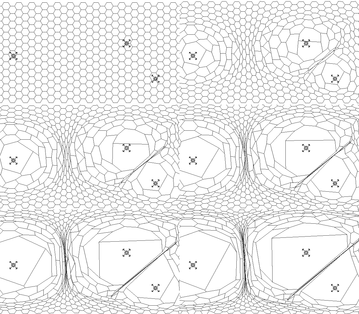
This is the animation of the t value, creating a tearing effect determined by the combined distances to the point charges.
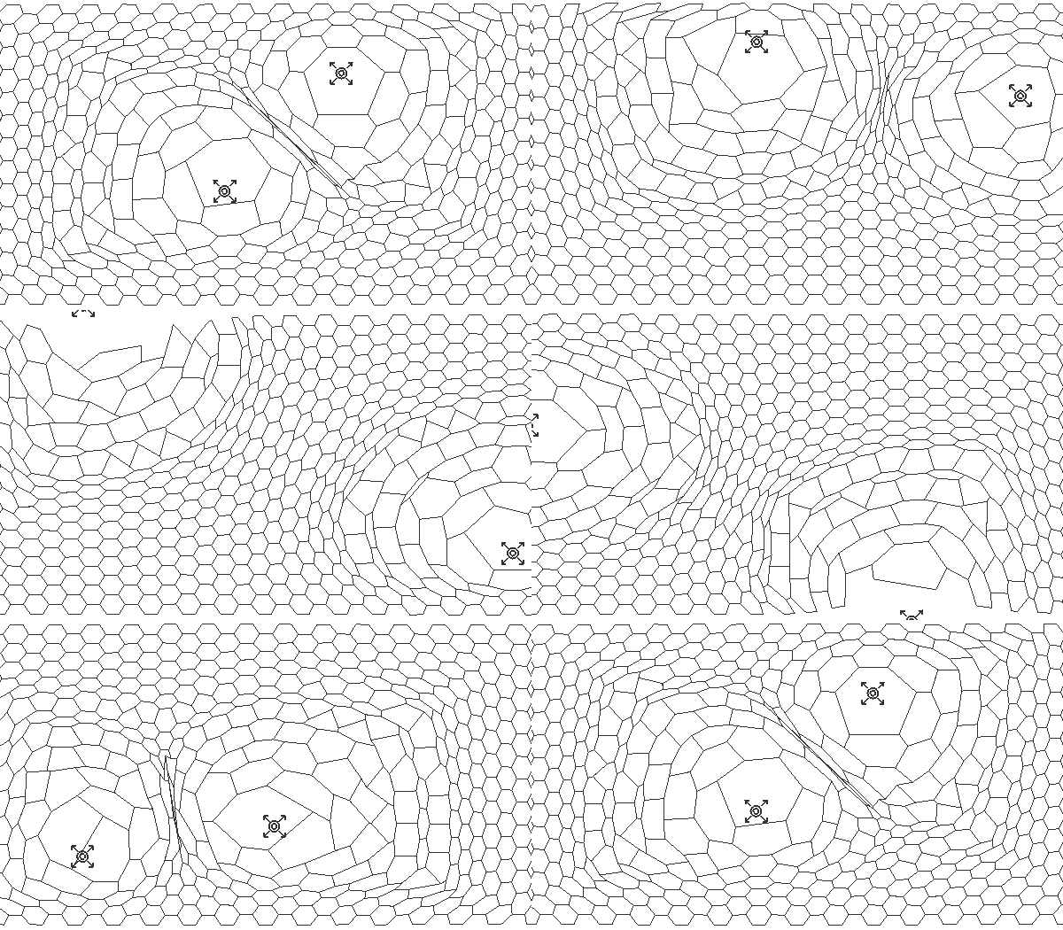
Of course, point locations are another subject of exploration.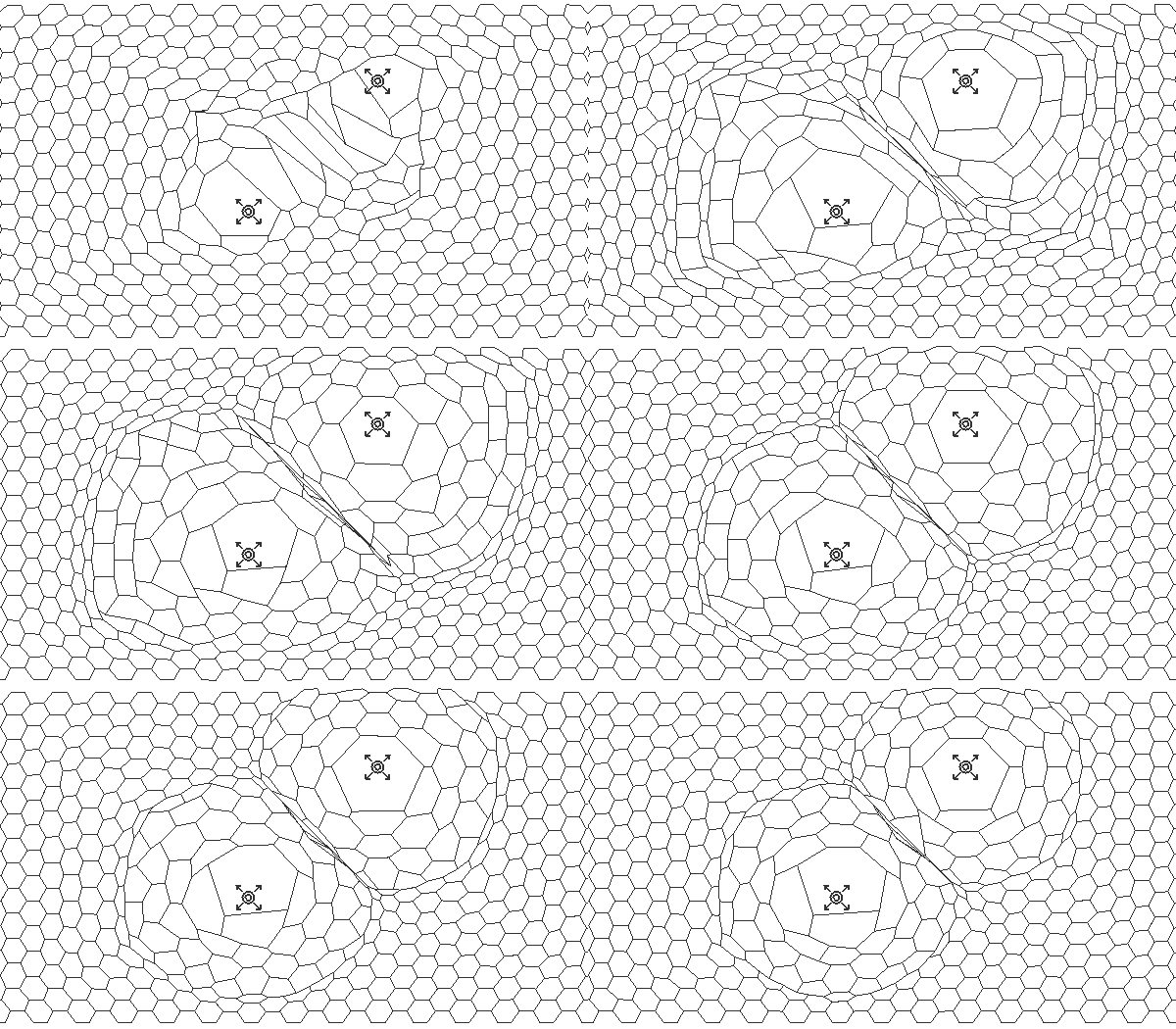
And the decay value of point charges introduces another effect. You can download the Grasshopper file below:
- Grasshopper: https://www.designcoding.net/category/tools-and-languages/grasshopper/
- [Image]: https://www.designcoding.net/decoder/wp-content/uploads/2012/12/2012_12_27-objectiles-def.jpg
- field line: https://en.wikipedia.org/wiki/Force_lines
- Download: https://www.designcoding.net/decoder/wp-content/uploads/2012/12/2012_12_28-objectiles2.ghx
Source URL: https://www.designcoding.net/vector-fields-basics/